I. General Principles of the Solution
1. Background
Communication towers are the core infrastructure of mobile communication networks, mainly including monopole towers, angle steel towers, three-pole towers, rooftop towers, landscape towers, and other types of fixed tower structures. These towers operate outdoors for long periods and are continuously exposed to natural environmental conditions such as strong winds, typhoons, heavy rain, ice accretion, frost, and salt spray corrosion. At the same time, they also face various safety hazards, including uneven foundation settlement, aging and cracking of concrete foundations, tower material corrosion, loose bolts, nearby excavation and construction activities, and landslides on surrounding slopes.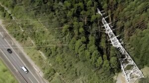
Traditional safety management mainly relies on quarterly and annual manual inspections, which present significant limitations. Minor structural tilts and gradual foundation settlement cannot be identified by visual observation, allowing hidden hazards to accumulate over time. In addition, on-site inspections cannot be carried out under severe conditions such as strong winds, heavy rain, or nighttime environments. Manual inspections are also characterized by delays and subjectivity, making real-time risk control impossible. Once hazards continue to develop, they can easily lead to tower instability, tower collapse, and structural failure, resulting in large-scale communication interruptions, equipment damage, casualties, and major economic losses.
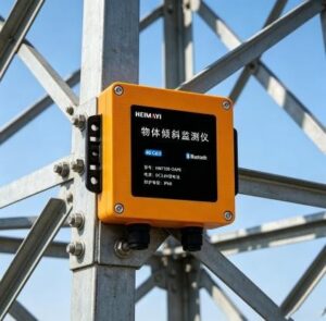
To comprehensively improve the safety management capabilities of communication towers and achieve early hazard prediction, proactive warning, and closed-loop incident handling, this solution introduces a high-precision Tilt Monitoring Device and a 24-hour fully automated intelligent monitoring system, fully meeting the safety management requirements throughout the entire lifecycle of communication towers.
2. Applicable Scope
This solution is applicable to all fixed communication towers operated by major telecom operators, including ground-mounted monopole towers, angle steel towers, three-pole towers, bionic landscape towers, guyed towers, rooftop fixed mast towers,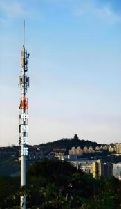 and rooftop ballast towers. It is suitable for various environments such as urban areas, suburban areas, farmland, mountainous slopes, coastal salt spray regions, and mining areas. The system can be routinely used for existing tower hazard monitoring, newly constructed tower safety management, special safety protection during flood and typhoon seasons, and monitoring of key sites exposed to geological hazards
3. Design Principles
- Non-Destructive Structural Principle: The equipment requires no drilling, welding, or cutting throughout installation and operation, ensuring that the original tower structure and anti-corrosion coating remain undamaged, fully complying with telecom tower operation and maintenance standards.
- Precision and Stability Principle: Industrial-grade high-precision sensing technology and intelligent anti-interference algorithms are adopted to distinguish wind-induced vibration from actual structural tilt, effectively eliminating false alarms and missed alarms. The backend algorithm can also rapidly analyze the direction and angle of inclination.
- All-Scenario Adaptability Principle: The solution is specifically designed to address various site conditions, including foundation settlement, weather impacts, construction disturbances, and geological hazards, ensuring reliable operation in harsh environments throughout the year.
- Unattended Operation Principle: Supports wireless transmission (and can also access base station network systems through an RS-485 bus), low-power operation, and fully automated data acquisition and analysis. It is suitable for unattended outdoor base stations and helps reduce manual maintenance workload.
- Long-Term Operation and Maintenance Principle: The device features strong weather resistance, low failure rates, traceable data records, and closed-loop maintenance management, making it suitable for long-term communication tower safety management.
II. System Overall Architecture and Equipment Selection
1. System Architecture
The system adopts a four-layer integrated architecture to establish a lightweight, highly stable, and easy-to-maintain intelligent monitoring system, enabling fully automated unattended operation throughout the entire process:
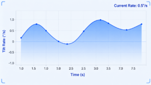
- Perception Layer: High-precision three-axis Tilt Monitoring Devices are used to collect real-time X-axis (east-west), Y-axis (north-south), and Z-axis (vertical) tilt angles and tilt variation rates of communication towers, enabling the detection of minor structural deformation.
- Transmission Layer: Utilizes 4G Cat.1 wireless communication or RS-485 bus transmission, featuring strong electromagnetic interference resistance and stable signal performance. The system is suitable for outdoor base station environments and supports offline data caching and breakpoint retransmission after network recovery.
- Analysis Layer: A cloud-based intelligent monitoring platform automatically aggregates data, generates deformation curves, analyzes tilt trends, filters interference data, and intelligently determines hazard levels.
- Warning Layer: Supports multi-level alarm notifications through PC monitoring platforms, mobile mini-programs, and SMS alerts, enabling real-time hazard warnings and closed-loop safety management.

2 Core Equipment Technical Parameters
| Category | Parameters | Functional Remarks |
| Measurement Accuracy | X、Y Axis: ±0.1°, Z Axis: ±0.5° | Capable of accurately detecting minor tilt and settlement that cannot be identified through manual inspection |
| Monitoring Dimensions | X、Y、Z Three-Axis Monitoring | Eliminates monitoring blind spots and accurately determines tilt direction and inclination angle |
| Intelligent Algorithms | Built-in wind vibration filtering, temperature drift compensation, and steady-state determination algorithms | Filters environmental interference data and prevents false alarms caused by external disturbances |
| Protection Rating | IP68 | Suitable for outdoor environments exposed to wind, frost, rain, snow, and dust |
| Enclosure Material | Flame-Retardant PC Housing | Effectively reduces the impact of lightning strikes |
| Power Supply Method | Wired power supply with battery backup support | Wired power is supplied from the base station power system to ensure long-term continuous operation |
| Communication Method | 4G Cat.1/RS485 Communication | Wireless communication eliminates complex cabling and enables highly convenient installation |
| Near-Field Communication | Bluetooth Communication | The device can be managed through a mobile app via Bluetooth connection at ground level, eliminating the need for tower climbing inspections |
| Installation Method | Fixed with galvanized stainless steel clamps | Compatible with all round-pipe and angle-steel tower structures, ensuring stable installation without long-term loosening. No drilling is required on the original structure, preventing damage to structural stability and anti-corrosion coatings |
| Tilt Threshold | Customizable | Alarm trigger thresholds can be configured according to project requirements |
| Operating Temperature Range | -40℃~+85℃ | Suitable for extreme high- and low-temperature environments across different regions |
| Anti-Interference Capability | Effectively shields electromagnetic and radio frequency interference from base station RRUs, microwave systems, and high-voltage power lines | Ensures stable communication performance |
III. Standardized On-Site Installation Implementation Plan
1. Precise Installation Location Selection
Based on the structural stress distribution and deformation characteristics of different tower types, monitoring locations are scientifically selected to avoid interference zones and ensure the authenticity and reliability of monitoring data.
- Monopole / Single-Pole Towers: Installed on the rigid main pole at approximately 1/2 to 2/3 of the tower height, avoiding high-frequency sway zones near the tower top and airflow disturbance areas around antenna cantilevers, thereby accurately reflecting overall tower tilt and foundation settlement conditions.
- Angle Steel Towers / Three-Pole Towers: Installed on the main structural columns at the middle-to-upper section of the tower body, away from cross arms, climbing ladders, antenna brackets, and other auxiliary loose components to avoid interference caused by localized vibrations.
- Rooftop Communication Towers: Installed on the rigid lower section of the tower structure, avoiding rooftop vibration areas and wind-induced antenna vibration zones, with a focus on monitoring tower deformation and rooftop foundation settlement.
- Restricted Installation Areas: Installation is prohibited at tower tops, antenna cantilevers, strong electromagnetic zones directly beneath microwave antennas, corroded or damaged tower components, and areas surrounding lightning rods.
2. Standardized Installation Procedure
- Surface Preparation: Clean dust, oil stains, rust, and moisture from the tower surface at the installation location to ensure a flat and dry mounting surface, allowing the device base to fully fit the tower structure without gaps.
- Positioning and Leveling: Properly align the monitoring device according to the specified installation direction in the installation manual, calibrate the horizontal reference, and align it with the east-west and north-south directions to eliminate initial installation errors.
- Fastening and Securing: Use dedicated galvanized clamps for locking and fixation to ensure uniform force distribution and secure fastening, enabling resistance to long-term wind-induced vibration and preventing device displacement or loosening.
- Protection Measures: Apply waterproof sealing treatment to device wiring ports and antenna connectors, and ensure antennas are positioned away from metal obstructions to maintain stable signal transmission.
- Stabilization and Calibration: After installation, allow the system to remain stationary for 30 minutes to ensure complete release of tower stress and stabilization of structural conditions, then perform the initial zero-point calibration and lock the monitoring baseline values.
- On-Site Commissioning: Test the device’s data acquisition, wireless transmission, cloud synchronization, and alarm notification functions to ensure normal operation, stable data output without abnormal fluctuations, and no latency or offline transmission issues.
3. High-Altitude Installation Safety Specifications
- High-altitude operations must strictly comply with telecommunications tower climbing safety regulations, with complete fall protection and electrical insulation equipment provided to prevent aerial work accidents.
- The entire installation process must be carried out without drilling, welding, or cutting, and any damage to the original tower structure or anti-corrosion protective coating is strictly prohibited.
- The device must be securely installed and properly oriented to ensure accurate and long-term stable monitoring data.
IV. Special Response Solutions for Full-Scenario Operating Conditions
1. Uneven Tower Foundation Settlement and Foundation Aging/Cracking Conditions
Operating Condition Description:
For aging communication towers, backfilled foundations, and soft farmland soil foundations, concrete foundations may experience weathering and cracking, while the surrounding soil may undergo creep deformation. As a result, the tower structure gradually develops slow unidirectional micro-tilting. These hidden hazards accumulate continuously and are difficult to detect through manual inspection, potentially leading to tower collapse accidents over the long term.
Response Measures:Enable the tilt rate trend monitoring mode to calculate deformation increments on an hourly and daily basis. During flood seasons and after rainfall, the monitoring frequency is automatically increased to generate long-term settlement trend curves. The system can provide early prediction of foundation instability risks, allowing timely corrective actions such as foundation grouting, crack repair, anchor bolt tightening, and foundation reinforcement after alarms are triggered.
2. False Alarm Conditions Caused by Sway During Strong Winds and Typhoons
Operating Condition Description:
Communication towers have large wind-exposed surfaces. During strong winds and typhoon conditions, high-frequency reciprocating elastic sway can occur. Conventional monitoring devices are unable to distinguish wind-induced vibration from actual structural tilt, resulting in frequent false alarms.
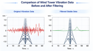
Countermeasures: Enable an intelligent wind-vibration filtering algorithm to automatically filter out high-frequency, small-amplitude, and repetitive wind-induced vibration interference data. Only continuous and unidirectional structural tilt deviations are identified as valid potential hazards. During typhoon periods, increase the monitoring frequency, record peak tilt-angle values, and maintain full-process cloud-based monitoring to eliminate false alarms.
3. Electromagnetic and Radio Frequency Interference Conditions at Base Stations
Operating Condition Phenomenon: The RRU units, microwave antennas, feeder cables on the tower, and nearby high-voltage power lines generate strong electromagnetic and radio-frequency radiation, which can easily cause monitoring data fluctuations, drift, and garbled signals, thereby affecting monitoring accuracy.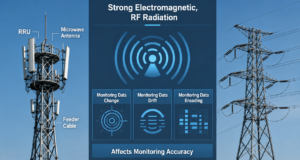
Countermeasures: Avoid installing monitoring points within the core microwave transmission areas. Equipped with multi-level software filtering algorithms to automatically correct abnormal data, ensuring stable and accurate monitoring data.
4. Disturbance Conditions Caused by Nearby Construction and Excavation Work
Operating Condition Phenomenon: Road construction, foundation pit excavation, pile foundation work, and earth backfilling around the base station disturb the original soil structure of the tower foundation, causing lateral foundation displacement and force imbalance, which may lead to rapid tower tilting. This is considered a sudden and high-risk potential hazard.
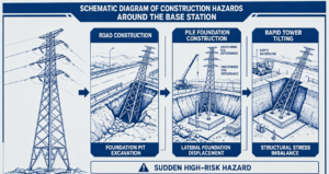
Countermeasures: Activate the accelerated rate warning mode to achieve second-level response to rapid tilt-angle changes. If deformation increases sharply within a short period, a high-level warning will be triggered immediately. Operations and maintenance personnel will be notified at once to order nearby construction work to stop, and to carry out slope support and tower foundation reinforcement measures to prevent the risk of sudden tower collapse.
5. Mountain Slope Geological Landslide Conditions
Operating Condition Phenomenon: Towers on mountain slopes are built relying on the mountain terrain. During the rainy season, rainwater infiltration may trigger shallow mountain sliding and slope collapse, causing overall tilting and displacement of the tower foundation. Such geological hazards are highly concealed and difficult to detect.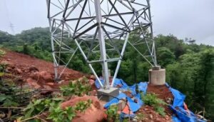
Countermeasures: Continuously monitor long-term tilt trends, and automatically strengthen monitoring intensity during the rainy and flood seasons. Combine rainfall data to analyze risk correlations and predict potential landslide hazards in advance. Archive abnormal data and include it in the geological hazard management database to support slope reinforcement and base station relocation assessment work.
1.1 Structural Conditions of Tower Material Corrosion and Bolt Loosening
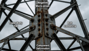
Operating Condition Phenomenon: Towers that have been in long-term service may experience tower material corrosion, connection bolt loosening, and component fatigue deformation, resulting in hidden minor tilting that is difficult to accurately detect through manual inspections.
Countermeasures: Rely on high-precision monitoring to capture minor structural deformations and accurately identify hidden potential hazards. Use trend data to distinguish between tower foundation settlement and tower body deformation, enabling precise fault localization. After warnings are issued, carry out targeted measures such as bolt tightening, rust removal and anti-corrosion treatment, and component reinforcement to complete the hazard management closed loop.
1.2 Unattended Outdoor and Weak Signal Conditions
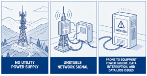
Operating Condition Phenomenon: In remote mountainous areas and outdoor base stations, the absence of commercial power supply and unstable network signals can easily result in equipment power failures, data transmission interruptions, and data loss issues
Countermeasures: The equipment features ultra-low power consumption and long battery life, eliminating the need for frequent charging. It supports solar complementary power supply and is equipped with an offline caching function, allowing data to be stored locally when there is no network connection. Once the signal is restored, the data will be automatically retransmitted, effectively preventing data loss.
V. Graded Warning Standards and Emergency Response Procedures
1. Three-Level Warning Determination Standards
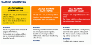
- Yellow Warning (General Hazard): Tilt angle of 0.3°–0.5°, or continuous slow displacement lasting for 24 hours. There is no immediate risk of instability, but minor structural or foundation hazards may exist.
Response Measures: Include the site in the key inspection management list. Conduct on-site inspections within 48 hours to check the condition of the foundation, bolts, and tower materials, while continuously tracking data changes. - Orange Warning (Major Hazard): Tilt angle of 0.6°–0.8°, with a continuously increasing tilt trend. The tower shows obvious structural displacement and poses a potential risk of instability.
Response Measures: Immediately suspend nearby construction activities and carry out a special inspection. Complete tower leveling, foundation reinforcement, and structural component strengthening within 72 hours. - Red Warning (Emergency Hazard): Tilt angle ≥ 0.8°, or a rapid and sharp increase in the tilt angle within a short period of time. The tower is on the verge of instability and may collapse at any moment.
Response Measures: Immediately cordon off the area, evacuate personnel, and shut down nearby operating equipment. Activate the emergency rescue plan and promptly carry out temporary support, reinforcement, or tower dismantling measures to prevent accidents.
2. Full-Process Emergency Response Procedures
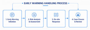
- Warning Notification: After the system triggers a warning, it will immediately send synchronized notifications through platform pop-up alerts, SMS messages, and mini-program notifications, clearly indicating the affected station site, tilt-angle data, and warning level.
- Hazard Assessment: Operations and maintenance personnel use cloud-based trend curves and real-time data to quickly determine the cause of the hazard, such as settlement, loosening, construction disturbance, or geological sliding.
- On-Site Response: Implement graded measures according to the warning level, including inspection and verification, construction shutdown control, reinforcement and rectification, and emergency rescue operations.
VI. Routine Operation, Maintenance, and Common Fault Troubleshooting
1. Routine Operation and Maintenance Management
- The system operates fully automatically on a 7×24-hour unattended basis, automatically storing data, generating operation and maintenance reports, and compiling hazard statistics.
- The equipment is equipped with a self-diagnostic function that monitors power level, signal strength, and operating status in real time, and automatically reports faults when abnormalities are detected.
- Before typhoon seasons, flood periods, and freeze-thaw seasons, carry out special inspections and calibration, including zero-point calibration and warning function testing.
- Quarterly On-Site Inspection: Manually inspect the tightness of the clamps, equipment waterproofing, and overall appearance integrity, and clean dust and debris from the equipment surface
2. Rapid Troubleshooting and Handling of Common Faults
- Device Offline or No Data: Check the base station network signal and device battery level, adjust the antenna angle, and restart the device to restore data transmission.
- Data Fluctuation or Drift: Check for electromagnetic interference and equipment loosening issues, re-tighten the installation surface, and perform zero-point recalibration.
- Frequent False Warnings: Enable the wind-vibration filtering algorithm, check whether there is local vibration interference at the installation point, and adjust the device position accordingly.
- Low Battery Warning: Conduct an on-site inspection of the battery level (applicable to battery-powered devices).
VII. Application Value of the Solution
- Safety Assurance: Achieve early prediction of tower tilting and settlement hazards, thoroughly preventing major safety accidents such as tower collapse, communication interruptions, and casualties, thereby ensuring the safety of communication infrastructure.
- Cost Reduction and Efficiency Improvement: Intelligent unattended monitoring replaces traditional high-frequency manual inspections, greatly reducing manpower and maintenance costs while compensating for monitoring gaps during nighttime and adverse weather conditions.
- Precision Operation and Maintenance: Utilize high-precision data to identify hidden hazards, avoid blind inspections and ineffective rectifications, and improve the refinement level of tower operation and maintenance management.
- Compliance and Traceability: Full lifecycle data is retained, hazards can be traced, and rectification records are fully trackable, ensuring complete compliance with operators’ safety operation and maintenance requirements, as well as flood prevention, wind prevention, and geological disaster control management standards.